LIQUID COOLING / FIT-CHECK DESIGN
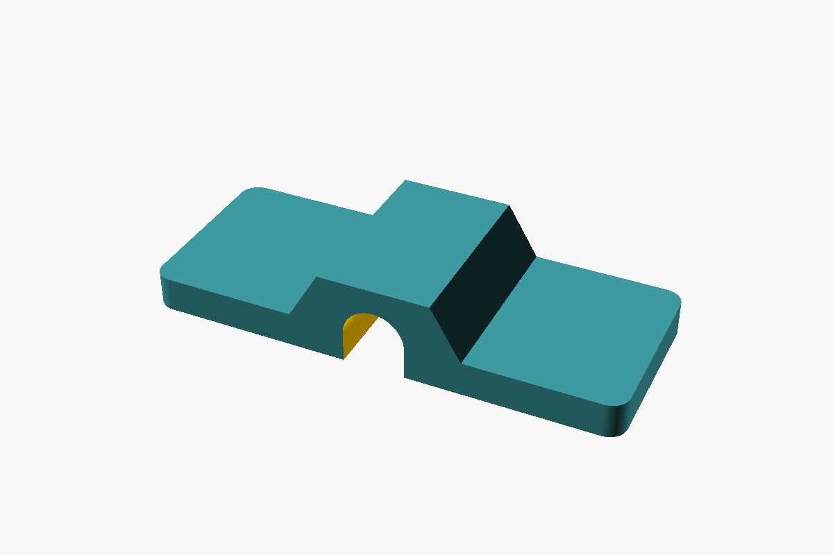
Detection rope bracket
Three footprints around one nominal 6 mm passage.
Explore dimensionsDESIGNED AROUND THE DETAILS
Practical design for the small parts that make an installation work. From leak detection rope brackets to your next on-site challenge.
Explore accessories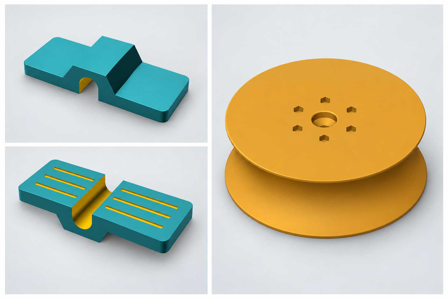
THE FIRST PART
Designed to sit over a floor-level detection rope, with broad feet and an open-bottom passage. Adapt the footprint while keeping the rope opening consistent.
RF / 001
Nominal 6 mm passage · Parametric design
Final material, printed clearance and adhesive compatibility are confirmed through fit testing for your installation.
Discuss this bracketACCESSORIES / DESIGN TO ORDER
LIQUID COOLING / FIT-CHECK DESIGN
Three footprints around one nominal 6 mm passage.
Explore dimensions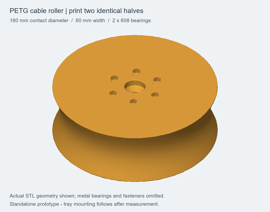
CABLE ROUTING / PROTOTYPE
A printable roller concept for a tray-specific guide. Mounting and working loads require validation.
Discuss a rollerCUSTOM DESIGN
Cable-management brackets, identification holders, spacers and installation jigs can start with a sketch and a set of dimensions.
Request a custom partBEYOND ONE PART
Explore brackets and supports around your detection rope route and installation constraints.
Bring the awkward routing, mounting or identification problem that an off-the-shelf part doesn't quite solve.
Discuss a repeatable task that could benefit from a purpose-made guide, spacer or positioning jig.
FROM SITE TO PART
A useful part starts with understanding where it needs to work.
Share the dimensions, mounting surface and operating environment. A sketch or photograph helps explain the constraint.
Turn the requirement into a printable model, with material and geometry chosen for the proposed use.
Evaluate a prototype for fit and function, then refine the design before agreeing a batch.
YOUR NEXT PART
Put the essentials into a design brief you can keep and share.